Mar 19, 2024
Unless you have infinite time and money, simulation will play a critical role in the development of any commercial drone platform or application. BUT the world of simulation is vast and technical, and you may just want to focus on the drone. Thankfully, solutions like MATLAB and Simulink exist, and better yet, MathWorks UAV Toolbox gives you a leg up for your drone-specific simulations. In this month’s drone software meetup, we invited Ronal George, Senior Application Engineer, Robotics, MathWorks, to give an in-depth rundown of the trio for you to get started quickly. This written guide will be broken up into two parts and summarizes the core topics covered during the meetup, but here’s the video if that’s your preferred format.
What MATLAB and Simulink Can Do
At the core of UAV development in MATLAB is the capability to accurately model the platform’s dynamics. No simulation can fully represent reality, but MATLAB’s first release was in 1984, so it has been battle-tested for almost half a century. Simulink acts as a comprehensive engineering sandbox, with a block-based editing paradigm that allows users to construct (or deconstruct) complex models quickly. Okay, but what does that mean for drone development?
A lot.
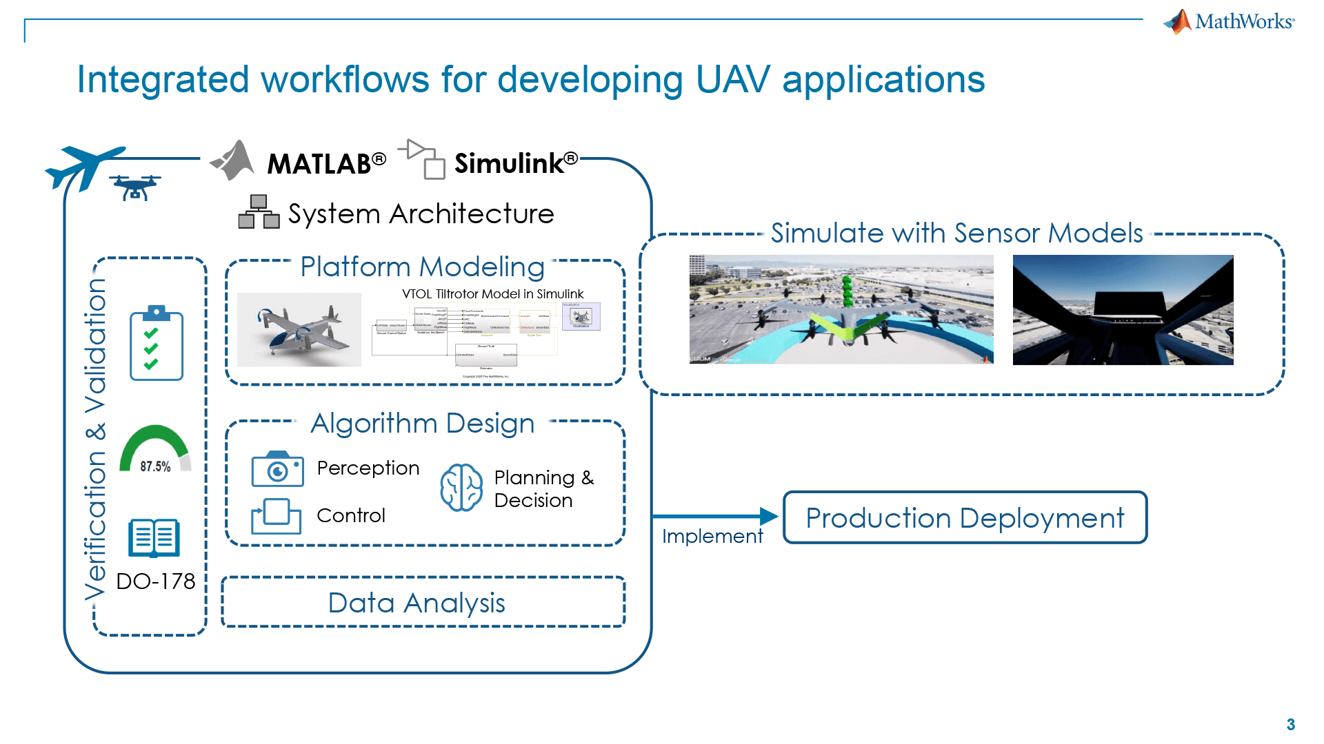
Between the two, you can combine simulations for your specific airframe (referred to as a platform), your sensor arrays, and your algorithm design for control, perception, planning, and decision-making. Also, it works in varied popular simulation environments like Gazebo and Unreal. Not to mention, if you are limited on resources, it can also work for low-fidelity cuboid simulations or Lidar.
You can deploy to multiple different hardware (basically anything that is ARM architecture), but in the case of drones, you probably only care about PX4 and the NVIDIA Jetson. For PX4, you will get direct access to the PX4 bus and on NVIDIA, you will have access to certain GP I/Os. Connections can be handled via MAVLink through any ground control station (GCS) that accepts that protocol, as well as directly to the drone if provided for.
Modeling Your Platform
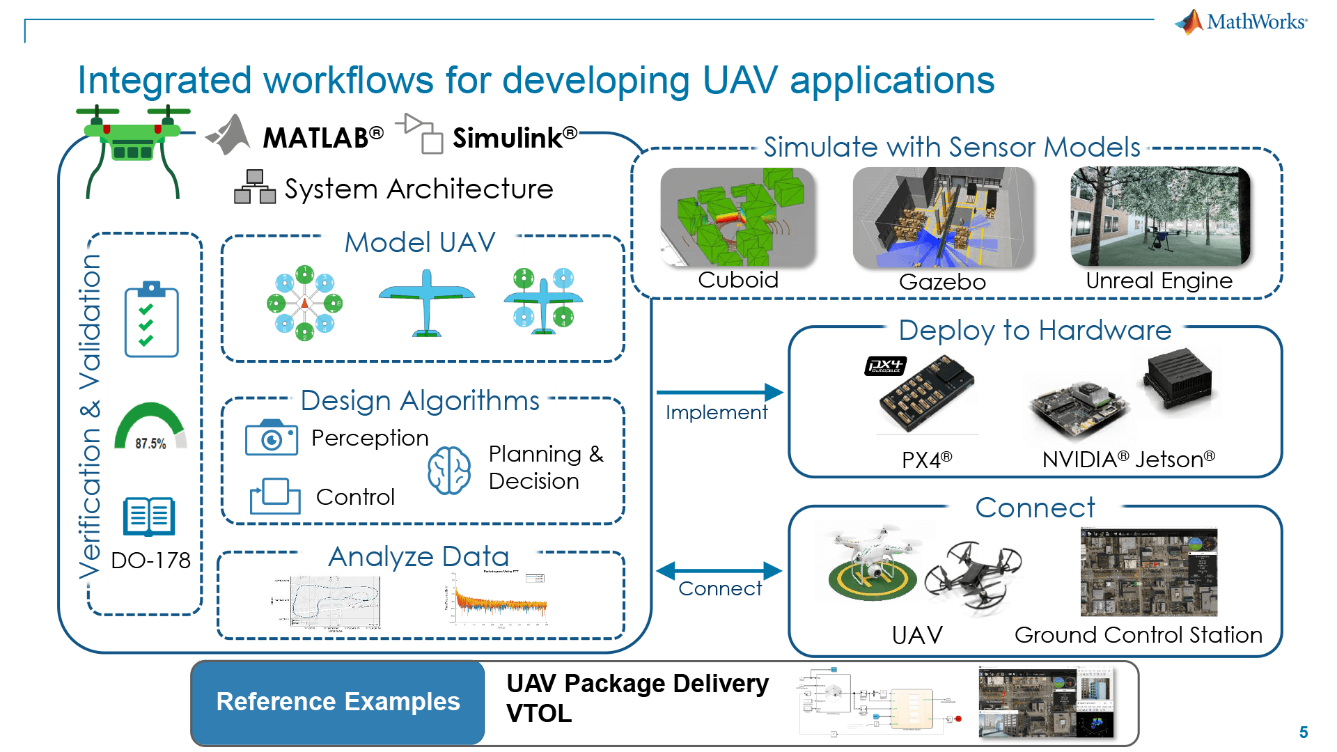
The essence of platform modeling in MATLAB/Simulink involves representing the dynamics of your UAV or drone within a simulated environment. You can represent this ranging from a simple model, such as a point mass in space subject to forces and moments, to more complex models that fully capture the dynamics of the data platform, including all physical interactions and behaviors the UAV may display during flight.
Levels of Fidelity
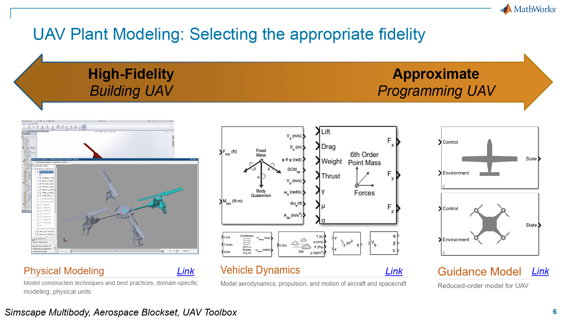
Guidance Model
The lowest level of fidelity would be a guidance model, which includes generic platform shapes for you to select from. Even at this level, you can customize environment-based commands such as gravity and wind.
Vehicle Dynamics
The vehicle dynamics level of UAV platform modeling occupies a middle ground in terms of complexity and detail. This level incorporates a more nuanced representation of the UAV’s movement and behavior. Here, the focus shifts to accurately simulating the dynamics of the vehicle, accounting for its responses to control inputs and environmental factors. This can include the UAV’s mass distribution, inertia, and how these factors influence its acceleration, deceleration, and ability to maneuver.
Physical Modeling
The highest level of fidelity starts truly from the ground up, giving you the ability to upload CAD models from popular platforms such as Autodesk, Creo, etc., for building models based on your actual platform’s design.
Autonomous UAV Algorithm Design Capabilities
Perception
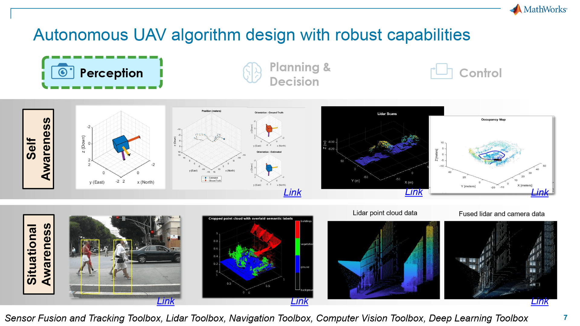
MATLAB/Simulink provides a comprehensive suite for developing perception algorithms, including sensor fusion, object detection, and environment mapping. With prebuilt algorithms and sensor models for lidar, radar, and cameras, engineers can simulate sensor outputs in photorealistic 3D environments or 2.5D simulation environments using UAV Toolbox. This enables UAVs to navigate complex environments, recognize objects or obstacles, and make informed decisions based on sensor data.
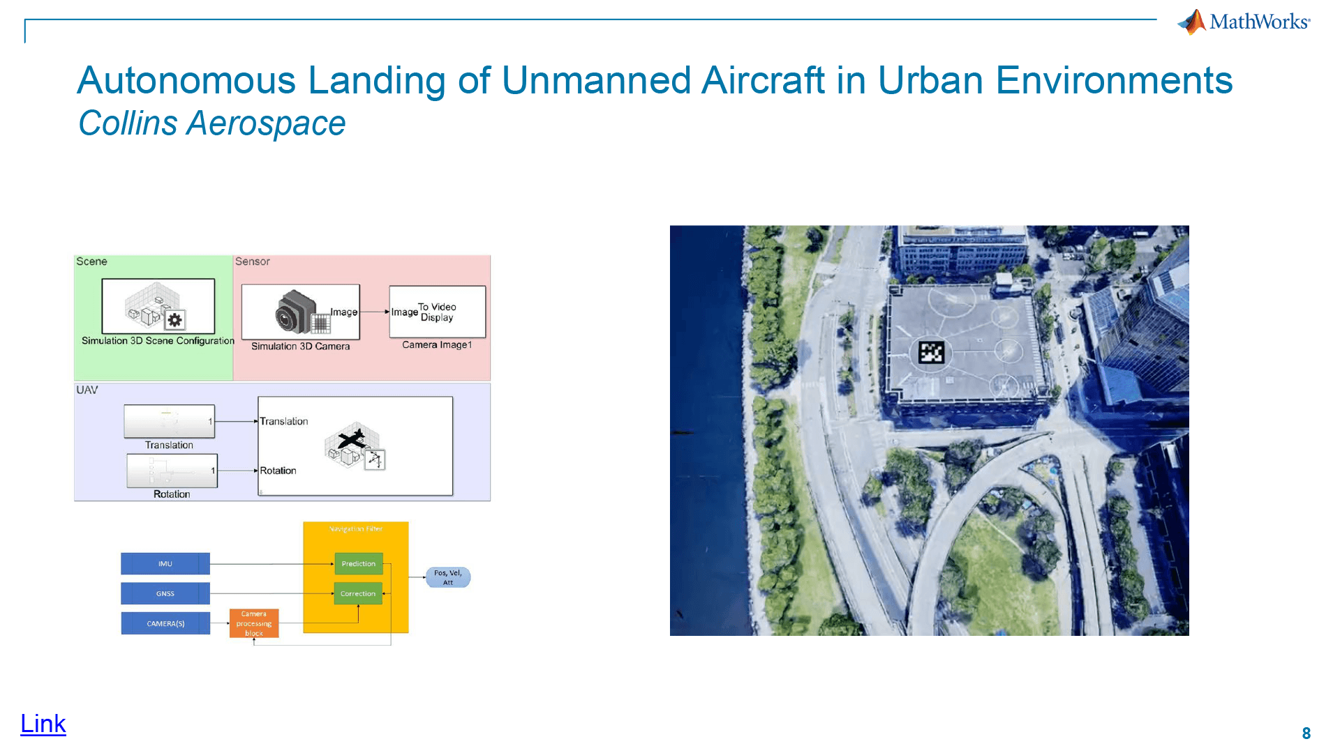
In the above example of a project done with Collins Aerospace by MathWorks, a QR code is used to determine a flight destination as well as to calculate the distance and angle of approach. This may seem like advanced stuff, but the solution was built out with a fairly low-fidelity model.
Planning and Decision-Making
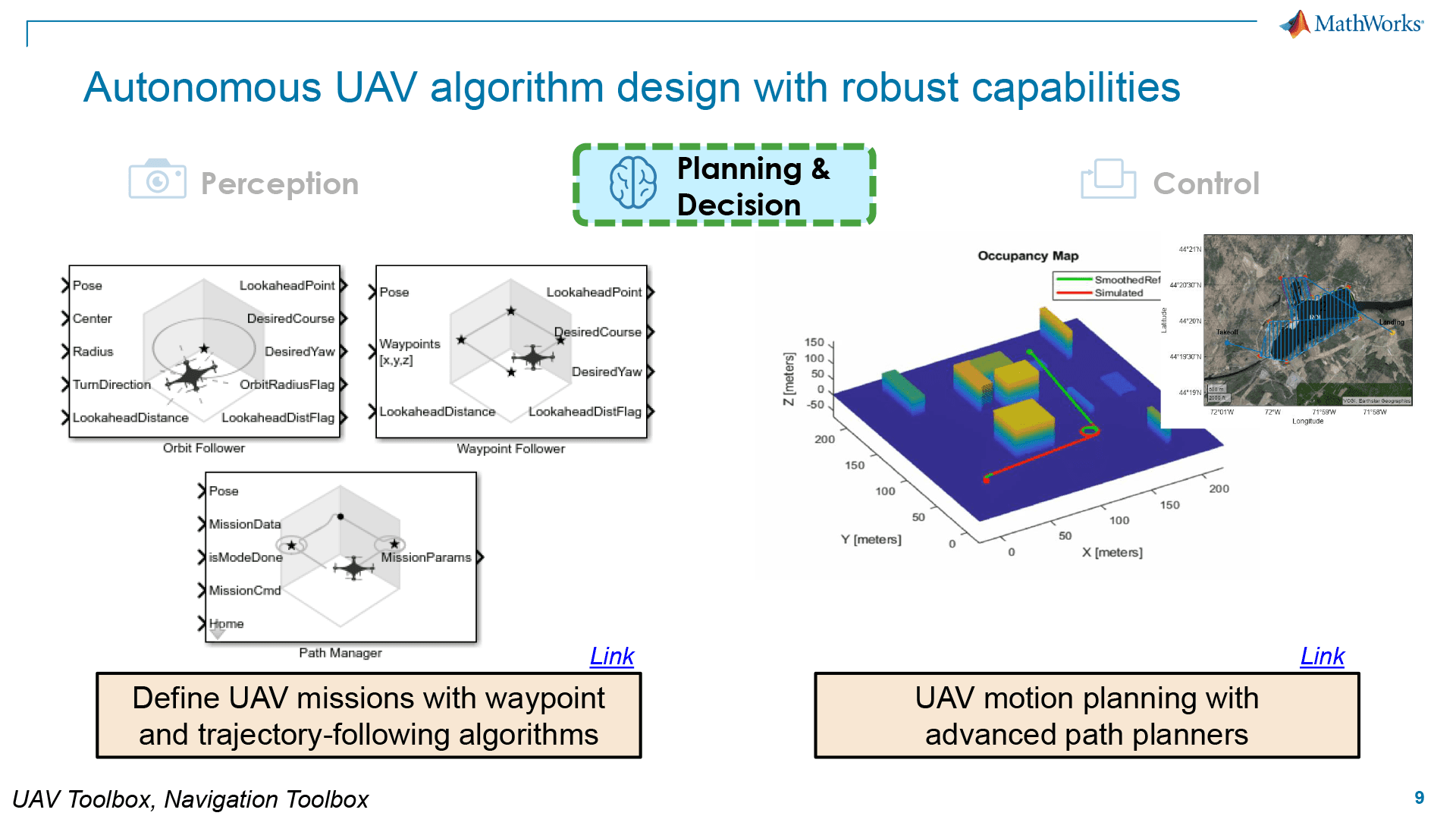
MATLAB/Simulink supports the development of algorithms for autonomous navigation, obstacle avoidance, and mission planning. Engineers can use MATLAB to develop algorithms for local and global path planners, vehicle motion behavior planners, and trajectory generation algorithms. The UAV Toolbox and Navigation Toolbox offer functions and blocks to model and simulate UAV algorithms, including waypoint following, orbiting, and customizable path planning algorithms.
Control
Engineers can model the UAV’s dynamics, design flight control algorithms, and simulate these with UAV plant models while including environmental factors. The ability to simulate control systems with accurate kinematics, dynamics, and contact properties allows for the refinement of control strategies to ensure stability and performance under different flight conditions. Additionally, MATLAB/Simulink supports Hardware-in-the-Loop (HITL) testing, enabling validation of control algorithms using actual hardware components, which we will get into later in this tutorial.
A Closer Look at Simulation Models
Don’t overlook the task of choosing the right level of complexity for your simulation. Depending on your stage of development or the task at hand, it’s important to be efficient when running simulations. As stated earlier, you have access to a range of choices from simple cuboid sims to Unreal engine and beyond.
Cuboid Simulation
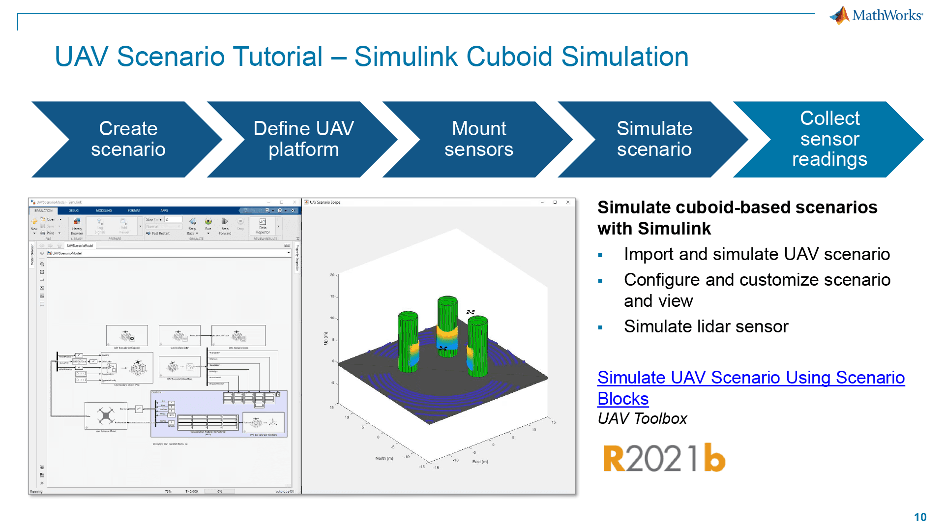
Simulink Cuboid Simulation provides a streamlined way to simulate UAV scenarios by using simple geometric shapes to represent vehicles and platforms. It makes it easy to generate the necessary sensor data for testing. It’s also perfect for use with Lidars and Radars for simplified obstacle avoidance.
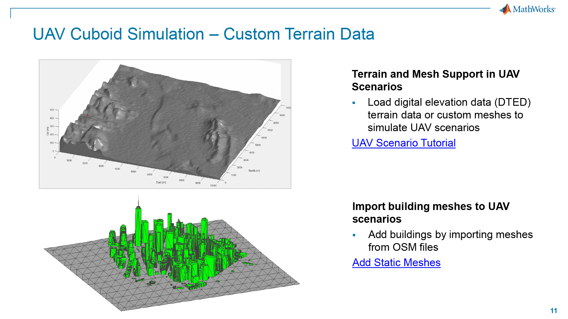
However, cuboid simulation goes deeper than that also. You have the ability to upload DTED terrain data or custom meshes or import Open Street Map (OSM) files for static meshes of buildings.
3D Simulation with Unreal Engine
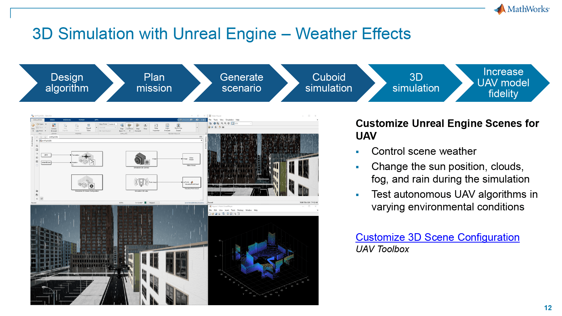
Combined with Simulink, Unreal Engine can act as a powerful tool for UAV developers, enabling them to create realistic simulation environments for testing and validating UAV systems. This includes the simulation of weather and lighting (sun position) for a more accurate representation of real-world operating conditions.
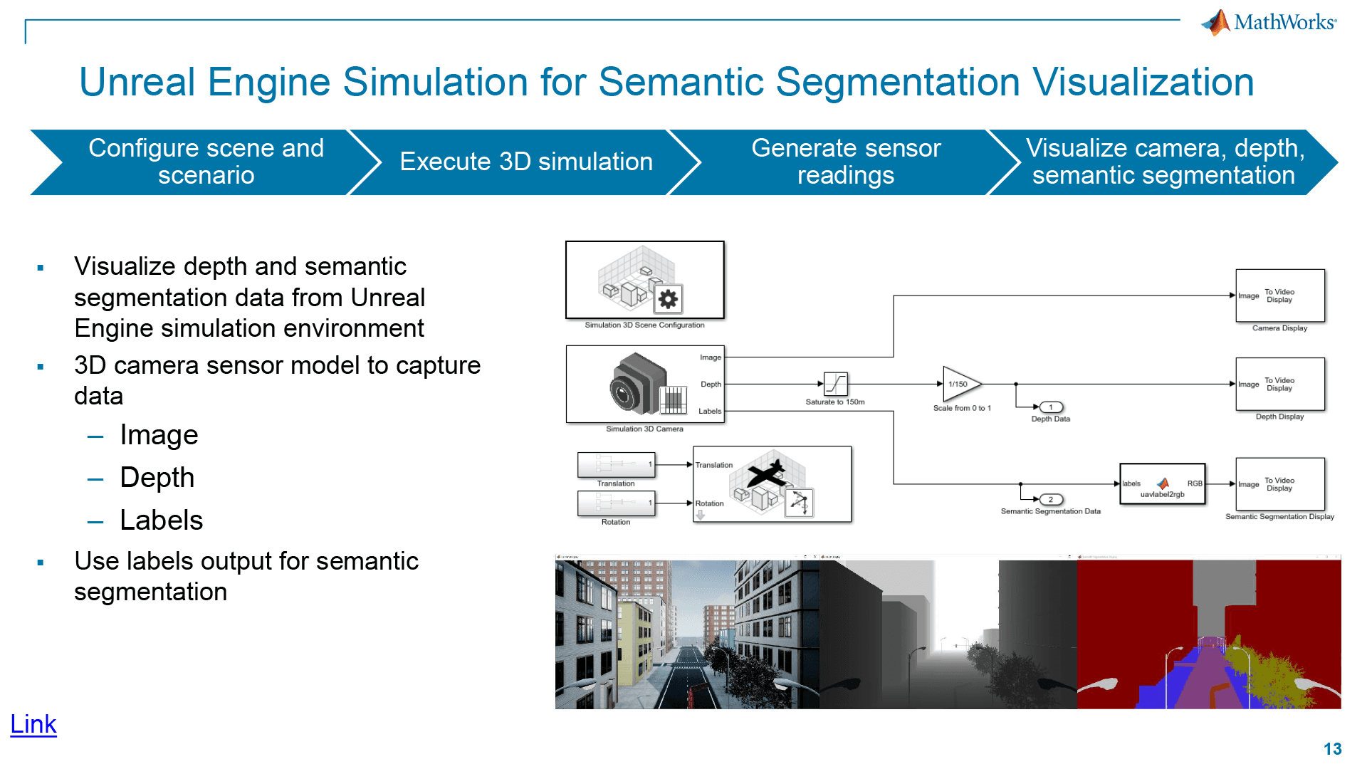
And that’s not the only benefit of integrating with Unreal. You also get enhanced classification capabilities. Semantic segmentation involves associating each pixel of an image with a class label, such as a road, building, or traffic sign. In the simulation environment, synthetic semantic segmentation data is generated according to a label classification scheme. This data can be used to train neural networks for UAV applications like landing zone identification. This provides a great baseline for training your own classification algorithms or testing the viability of one you have sourced from a third party.
Flight Log Analyzer
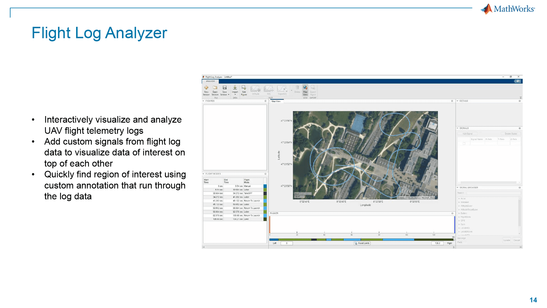
Flight logs act as the cornerstone of debugging UAV platforms. The UAV Toolbox’s Flight Log Analyzer allows you to visualize and analyze flight telemetry logs, stripping away hours you could spend scrolling through text logs or analyzing the data with custom tools.
Conclusion
As you can see in this overview of MATLAB/Simulink and the UAV Toolbox, MathWorks offers a comprehensive suite of tools for simulating drone flights at every degree of resolution and complexity you might need for your project. In Part 2, we will work on building out an actual workflow from start to finish using The Cube Orange.
